To LCD or not to LCD: befriending the ILI9163
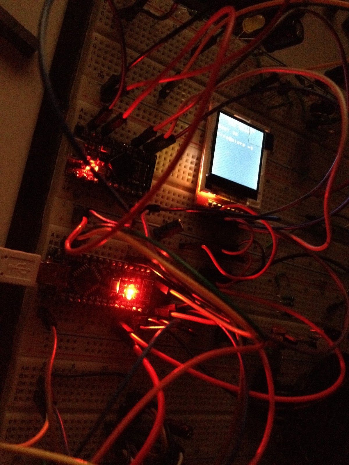
In this first blog post, I’ll talk a bit about my experience with the very cheap 1.44” 128x128 LCD available from eBay (also marketed as “Nokia 5110 LCD”), as well as other similar sites, and interfacing it to an Arduino Pro Micro board, also available from eBay, using own hand-written assembly code.
Gathering intelligence
The first thing you might notice about this product is that neither the product listing nor the actual PCB give any clue about how to talk to the display driver, or in fact, what kind of controller has been used at all. Fortunately, a simple Google query (I’ve found it very reliable to just search for <part name> arduino to learn about how to interface with something) revealed that the controller IC is an ILI9163C. Sumotoy’s library for interfacing the LCD from Arduino also turned up, but I decided not to use it for the time being and to roll my own code from scratch. In part because I had no interest in using the Arduino software framework in the final project and also because I saw this as an interesting little challenge.
The nice thing about the ILI9163C is the fact that finding the datasheet is trivial. The less nice thing is how bad the datasheet is. For a rather complex IC like this, the datasheet is poorly organized (there is no PDF index and the ToC lists all topics as being on page 4), often unclear and clunky, and contains tons of typos and copy-paste errors. Then again, for the price…
In any case, it turns out that the IC supports several serial and parallel interfaces and the choice of which to use is left to the product designer (in this case author of the “red PCB”). It wasn’t hard to figure out which of the interfaces was used here and which pins in the datasheet correspond to the 8-pin header on the board.
| datasheet | LCD PCB | MCU | purpose |
|---|---|---|---|
| – | LED | tied to 3.3 V | LCD backlight power supply; on-board 100R series resistor |
| SCL | SCK | SCK | SPI clock |
| SDA | SDA | MOSI | SPI data, half-duplex |
| WRX | A0 | digital output | toggle between command (LOW) and data (HIGH) mode |
| RESX | RESET | digital output or tied high | pull low for HW reset |
| CSX | CS | digital output (or tied low ?) | pull low to initiate communication |
| – | GND | GND | common ground |
| – | VCC | tied to 3.3 V | supply power for LCD & driver |
An important thing to note here: the driver IC only allows 3.3V on any of its pins and is not 5V-tolerant! If you hook it up directly (e.g. without using a level shifter) to your Arduino, you MUST NOT plug into USB or use an external power supply with the onboard 5V regulator. (I haven’t personally tested how quickly the IC gets damaged when subjected to such voltage, but decided not to push it)
What I did is use an external 3.3V linear regulator, powered through USB from a different board, with its output hooked up to the “5V” pin on the Arduino. This meant that every time I wanted to reprogram the Arduino through USB, I had to pop it out of my breadboard. Slightly annoying, but acceptable.
Out of laziness and to achieve maximum performance, I kept using the onboard 16 MHz oscillator even at this reduced operating voltage. I realize that this is out-of-spec for the ATmega32U4 and I won’t be surprised if it suddenly stops working one day, but so far I haven’t had any issues.
First contact
With the hardware set up, it was time to get into writing the software. My initial blind attempt to just pull the Data selection pin high and shove random data through SPI wasn’t met with success. Although I later found out that the SPI peripheral was never getting initialized because of a typo, this wouldn’t have worked anyways. Therefore I set on a painful journey through the datasheet. I learned about the 3 color modes supported by the driver. Out of 12-bit, 16-bit and 18-bit, I picked 16-bit, because it’s an integer multiple of 8 bits - the only SPI transmission size supported by the ATmega. If there was an 8-bit option, I would’ve probably gone with that despite the low color count, but in the end I’m glad I couldn’t.
Finally I figured out the minimal startup sequence to get the display to show something:
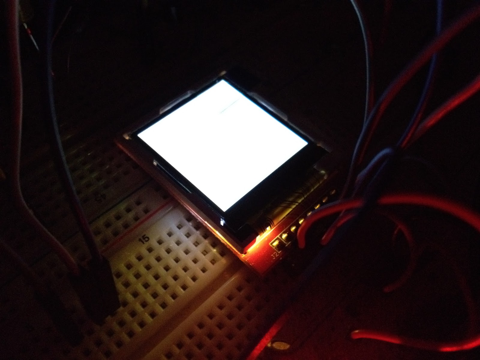
- reset the IC by pulling RESET low, waiting 1ms, pulling RESET high and waiting 120ms (might not be strictly necessary, as the IC seems to have a defined power-on state)
- issue the SLPOUT (exit sleep mode) command and wait for another 120ms
- issue the DISPON (display on) command and wait for 1ms
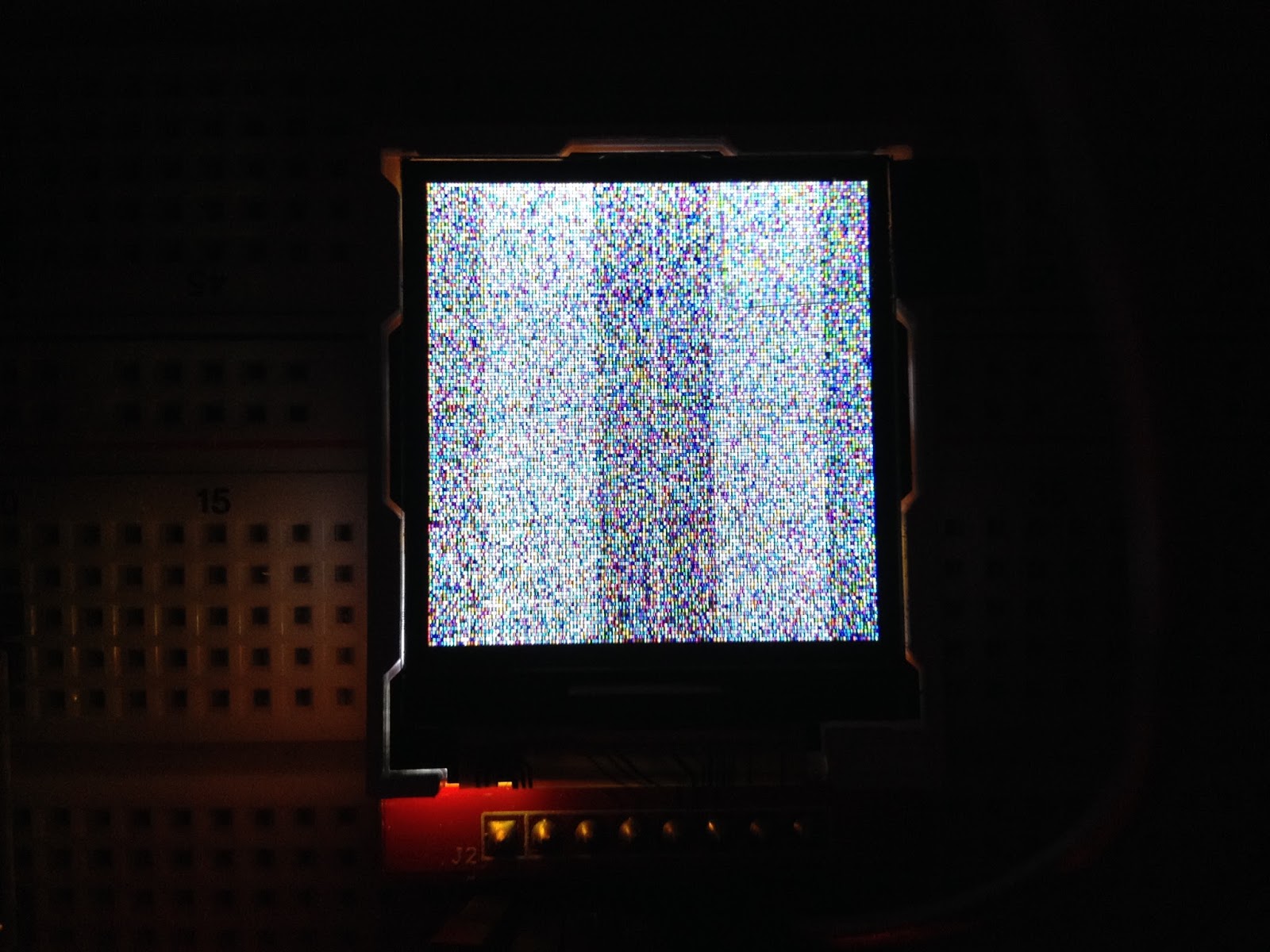
At this point the display lit up, beautifully visualizing the beautiful garbage of an uninitialized RAM. Truly a sight to behold. The next steps to get something meaningful out to the screen, are:
- select 16-bit color mode using the COLMOD command with 05h as its sole argument
- specify the area to draw into using CASET and PASET (also referred to by the datasheet as RASET – talk about consistency!)
- issue a RAMWR command and start pouring in the pixels (don’t forget to hold D/CX high)
Note that there are no commands to draw graphical primitives - only “overwrite the specified rectangle with the following pixel data”.
Blue shift
When I drew a 100x100 square in the middle of the screen this way, I noticed that it was shifted up - the first 32 lines were skipped, and the visible 96 lines of the image were followed by random garbage. Offsetting all PASET calls by 32 pixels did the trick - for now. Another thing I noticed was that the red and blue channels were swapped. After carefully comparing my SPI code with the datasheet, I concluded that the panel indeed uses the opposite channel ordering. Fortunately the driver has a command to remedy this; it’s called MADCTL and it also allows you to flip the LCD horizontally and vertically - which rotates the image by 180 degrees and seems to solve the 32px offset issue. That is, until you try to use scrolling.
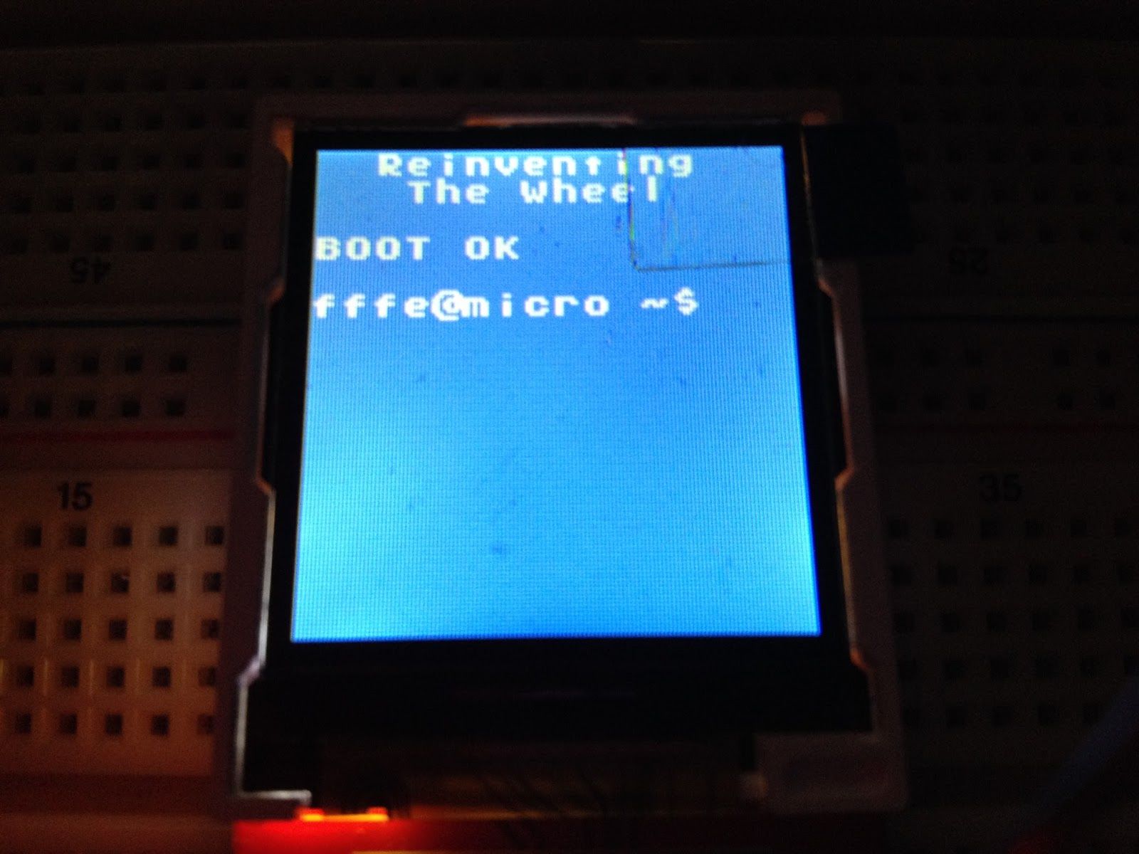
At this point I was able to consistently fill the screen with stuff and could as well shift my focus to other things. However, there was one other feature I wanted to explore…
The Elder Scroll
When wading through the datasheet, I noticed references to horizontal and vertical scrolling. However, the horizontal scrolling bits are mere placeholders for unimplemented features. Vertical scrolling, on the other hand, is actually a thing and there are commands to set it up. The datasheet couldn’t be more ambiguous about those, and I was very confused about which part of RAM gets drawn where. In theory, you divide the screen into 3 vertical parts, called Top Fixed Area, Scroll Area and Bottom Fixed Area. Using another command, you can change which line of Scroll Area is drawn first and thereby scroll the picture.
When I naïvely tried to do exactly that, nothing happened at first. After some tinkering, I found out that the sum of heights of the 3 areas needed to be 160px – not 128px as one might expect. Still, with different scroll amounts the behavior wasn’t what I’d call consistent. With values less than 32, nothing happened at all. Because of the 32px shift, I also had to waste the top 32 lines of the framebuffer to make the Top Fixed Area visible on the screen.
At this point, I decided to look into the aforementioned Sumotoy’s library, hoping to find a solution. Soon I found out the reason for this madness. Apparently, the “red PCB” version of the LCD+driver combo is wired incorrectly, so the ILI9163C thinks it’s actually dealing with a 160x128 panel! This explains why some lines were missing and others were shifted. It also partially explains the weird scrolling behaviour. What seems to work is using Scroll Area only and offsetting the scroll amount by 32. This has the benefit of allowing you to use 32 lines of off-screen buffer space to prepare sprites and text while scrolling. However, if you write code that relies on this, it will be incompatible with the “proper” version of the PCB (apparently the black one). Ugh.
Conclusion
It took about one afternoon to get this setup working. Thanks to Sumotoy’s library, I have a reference to check my code against when I run into issues.
The ILI9163C has many other features which I haven’t found the time to try out yet. If you have, please let us all know how it went - and how broken they are!
The code I’m using for driving this IC can be found here. A good driver would be portable, universal, complete and optimized. This one is neither, as it’s tailored to my project and any optimization at this point would be premature. Still, I hope it might be of use to somebody. Alternatively, you can point at it and laugh.
Some more things to explore:
- using software reset only, thereby saving one GPIO pin
- reading data from the Frame RAM – or rather reading anything at all
- how to do fast 3D graphics with an ATmega